OPTICAL JOINERY WAVE
14 weeks
group project
university of virginia
fall 2020
kuka prc code generator + rhino + grasshopper + fusion 360
kuka milling + fabrication + parametric modeling + pavilion design
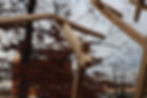
Starting from a study of traditional Japanese joints, this project was conceived to understand how a joint which is used in one plane can be redesigned and applied to a parametric structure. To achieve the intricate cuts required of a 5-axis cross-lap joint, a Kuka robot was used to mill each piece. The overall form of the structure creates the form of a crashing wave, exploding from what appears to be a simple frame of a square. The structural capabilities of the 5-axis cross-lap were stressed in long cantilevers at one end which were counterbalanced by cables to the ground.
Proposing a Form
The process of designing the form came from an iterative and parameterized process. We wanted the form to reflect the progression of the joint from a three-axis joint to a five-axis joint, gradually increasing in complexity and cantilever length along the course of the site path.
Utilizing grasshopper and visual parameterized tools, we were able to create iterations of the form to reflect the geometry of the site as well as the limitations of the joint.


Kengo Kuma Prostho Museum
Kengo Kuma
Kengo Kuma was extremely influential in the early developmental stages of this project, particularly his work with the GC Prostho Museum. This project consists of a lattice of chidori joints that aggregate in 3 dimensions. Our aim was to begin transforming the geometry of the chidori by warping the square cell into a less regular shape.
Chidori Diagram
EKKO Installation
This project takes a standardized form and through incremental rotation along a path suggests motion and curvilinear shapes. Our project similarly draws upon the formal language of sectioning and transformation for our pavilion.

Sculptural Pavilion
This installation designed by Kengo Kuma utilized traditional Japanese joinery techniques. A field of parallel beams connects with a cross-lap joint to build a volume that extends up.
The crosslap joint was rotated 90 degrees to create an aggregated mass. Our project would take this idea and propose a joint that rotates around additional axes..

KUKA Robotic Milling Process
The milling process was highly reliant upon computing all toolpaths prior to milling. Each toolpath for both ends of each beam was individually computed.
Toolpaths were generated in Grasshopper through a 2-step process. Once the joint was calculated by subtracting overlapping material, the resulting void was used to calculate toolpaths.

Milling in 3-Axes
The 3-axis cross-lap is so named because of the milling method which only requires movement of the mill in 3 axes. The more simplistic of the two, the 3-axis joint is milled from above and produces identical joints in both connecting beams.

Milling in 5-Axes
Due to the more complex intersections of the 5-axis joint, milling requires the robot to pivot in two additional axes. Rather than orient perpendicular to the world XY plane, the 5-axis joint requires the endmill to orient relative to the bottom plane of the intersection. The group experimented with various methods of milling this joint including swarfing material, but determined that a process similar to the 3-axis method of milling produced the fewest complications when irregularities in the intersection occurred.

Base
The base not only adds structural support to the cantilever, but also protects the sections from lateral movement. Our group iterated solutions to the base, but settled on one which would allow us to move the perpendicular support beam to achieve our desired angle.


Dove Tail Joint

Tongue and Groove Joint

Wedged Joinery
Context
The project started with research into case studies which set the direction and mission of the project. We were interested in systems of aggregation and particular joints, as well as the effects of transformation in the global form.
Because our group began our exploration through the lens of Japanese joinery, we focused early on joints which leveraged high tolerance joints to secure pieces of wood together. We wanted to know how robotic milling could allow us to push the limits of a simple joint, transforming it into something much more complex.
Proposing a Joint
At the start of the semester we looked extensively at examples and precedents of various joinery techniques. A good deal of the research and prototyping had to be conducted virtually due to the circumstances of this semester.
As we came into the studio to practice working on the wood joinery techniques we performed a brief exploration of joinery systems.

Mortise + Tenon
The Mortise and Tenon joint is known for its strength and creating a flush surface when built with precision. This joint is incredibly strong perpendicularly however it can occur at other angles. We considered this joint for our project, however decided against it based on the global form we decided to use.


Chidori
The Chidori joint is named after the Japanese wooden toy consisting of 3 elements that are cut uniquely and join together by twisting various components. Architects today like Kengo Kuma have used the joinery technique to construct tsugite joints in timber resulting in surprisingly strong joints. This joint was not chosen due to the rotation required to lock into place and the quantity of material needed to construct a lattice-like volume.


3-Axis Crosslap
The 3-Axis crosslap joint is a technique in which you subtract halfway through both widths of the wood at the same mirrored angle. This type of joint is easily cut with the typical cnc router as it requires the head of the mill to rotate only in 3-axes.


5-Axis Crosslap
The 5-Axis Crosslap Joint is defined by the 5-axes of rotation needed to mill the joint. Whereas the 3-axis crosslap joint sits in one plane, this joint breaks from the plane and creates more complex intersections. A similar process to the 3-axis is used to calculate intersections.; a plane is created at the center-point of the intersection and a vector for slotting each beam together is defined. Material is subtracted along that vector to allow for the pieces to slot together.


Input curves
Curves divided according to sine curve
Center lines between points
Extrusion along lines

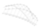
Global Form Iterations


Computing Toolpaths
The script uses input curves derived from the edges of the intersection and resulting void of each beam. The first operation offsets the short edges of the bottom plane of the subtracted geometry by a distance determined by the endmill width. Additional toolpath lines parallel to those offset array between the two outer edges and are then connected to form a zig-zag pattern. The zig-zag which sits on the bottom plane is then arrayed along the z-vector, which is determined by the depth of the void.
Fabrication
The fabrication process consisted of harvesting and sourcing the wood locally in Ashland, Virginia due to our requirement of a 2x2" beam. We then created a custom jig that secured and supported the beam during the milling process.
The base of the final pavili was made up of 2 by 4 beams connecting and resting upon the ground. Several cables were also used to better support cantilevers for safety.

Custom Jig
The jig allowed for the robot to cut multiple cross lap joints at once. This would speed up the milling process and save valuable time. This also allowed us to properly mill the 5-axis joints because the jig was set up to prop the wood up 6” and this let the robot mill at almost any angle.


Cable System
For safety, we decided that for the larger cantilevers we would fasten them down using ⅛” chain as well as a large metal stake which we purchased from Lowes.